
Page 37 - CE_Industral_Journal_2014
P. 37
and test injection is compact and lightweight for easy MEASURING THE CT DATA
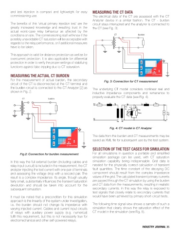
commissioning use. The electrical data of the CT are assessed with the CT
Analyzer device in a similar fashion. The CT - burden
The benefits of this ‘virtual primary injection test’ are the circuit stays interrupted and the analyzer is connected to
greatly increased knowledge and resulting trust in the the CT (see Fig. 3).
actual worst-case relay behaviour as affected by the
conditions on site. The commissioning staff will know if the
possibly unavoidable CT saturation will be acceptable with
regards to the relay performance, or if additional measures
have to be taken.
This approach is valid for distance protection as well as for
overcurrent protection. It is also applicable for differential
protection in order to verify the proper settings of stabilizing
functions against false tripping due to CT saturation.
MEASURING THE ACTUAL CT BURDEN
For the measurement of actual burden, the secondary Fig. 3: Connection for CT measurement
circuit of the CT is disconnected at the CT terminal and
the burden circuit is connected to the CT Analyzer [2] as The underlying CT model considers nonlinear real and
shown in Fig. 2. inductive impedance components and remanence to
properly evaluate the CT data (see Fig. 4).
Fig. 4: CT model in CT Analyzer
The data from the burden and CT measurements may be
saved as XML file for subsequent use by the test system.
SELECTION OF THE TEST CASES FOR SIMULATION
Fig.2: Connection for burden measurement For all simulations in question a portable and simplified
simulation package can be used, with CT saturation
In this way the full external burden (including cables and simulation capability being indispensable. Grid data is
relay input curcuit) is included in the measurement, the CT needed for the physically correct calculation of transient
analyzer injecting the test current with one pair of terminals fault quantities. The time constant of the decaying DC
and assessing the voltage drop with a second pair. The component should result from the complex impedance
result is a complex impedance. Its angle, though usually values of the grid. The calculated transient primary currents
fairly small, substantially influences the transient saturation are passed through the CT simulation by using the burden
devolution and should be taken into account for the and CT data from the measurements, resulting in realistic
subsequent simulation. secondary currents. In this way the relay is exposed to
test signals that closely relate to secondary currents that
It must be noted that a precondition for this simulation would have been achieved by primary short-circuit tests.
approach is the linearity of the system under investigation,
i.e. the burden should not change its impedance with The following time signal view shows a sample of such a
varying injected current. Cables and current input circuits simulation that clearly shows the saturation effect of the
of relays with auxiliary power supply (e.g. numerical) CT model in the simulation (see Fig. 5).
fulfill this requirement, but this is not necessarily true for
electromechanical and other self-powered relays.
INDUSTRY JOURNAL 35