
Page 39 - CE_Industral_Journal_2014
P. 39
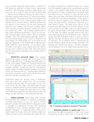
stays at its level, should be a rare situation - normally CTs   at a highly increased R for a short time span. Fig. 7 shows
        can always be selected in a way to avoid steady-state   how the impedance trajectory, for a quite heavily saturated
        saturation. One exception could be a weak feeder from   current  in  the  transient  state,  enters  from  the  right  and
        a bus bar with a small CT fitting the nominal feeder data   first reaches an X (mark 1) slightly below the steady-state
        - if several strong infeeds to the bus bar feed a fault on   fault  value  but  at  an  R  about  10  times  as  high  as  the
        the weak outgoing feeder then its CT might show steady-  steady-state fault value, then (after a time usually too short
        state saturation. The problem with this is that, whatever the   to actually trip) continues by wandering to even higher R
        relay’s interpretation of this corrupted signal shape is, will   and about twice the target X until it changes its direction
        stay like this for the fault duration. Blocking derived from   toward the target (mark 2), traversing in loops that go to
        the  amount  of  2nd  harmonic  will  fail  since  symmetrical   even  higher  X  values.  This  takes  about  180  ms  in  this
        saturation  only  contains  odd  harmonic  numbers.  Much   example and, depending on the R and X setting of the trip
        more common is transient saturation, present as long as   zone, will lead to a trip delay of about the same duration if
        the transient DC offset - that is always present when a   the upper zone boundary is not far above the steady-state
        fault current otherwise would have to ‘jump’ from the pre-  X  of  this  fault.  For  slightly  changed  data  the  first  low-X
        fault to the fault value at fault inception - has not noticeably   peak might actually trip an instantaneous zone 1 while the
        decayed. Since this offset depends (amongst others) on   steady-state fault impedance really is in zone 2, a kind of
        the current phase angle at fault inception it will differ in the   false trip one might not expect from a current ‘reduced’ by
        three phases for a three-phase fault, so the effect on the   CT saturation. So for distance relays in transmission as
        relay also depends on the implemented or selected inter-  well as distribution grids this test is really worthwhile. This
        phase  treatment  (cross-blocking).  For  two-phase  faults   example  also  shows  how  severe  a  transient  saturation
        the effect is the same in both phases since the currents   can be although there is no steady-state saturation at all.
        are just mirror currents to each other. Now let’s have a
        look at some protection principles and possible effects of
        CT saturation:

         1.    Definite-time  overcurrent  stages:  They  typically
        trigger phase-wise on the peak value of the current. Their
        setting is calculated from the steady-state RMS value, i.e.
        for non-offset signals. Stages with threshold settings that
        are  in  the  magnitude  of  fault  currents  that  could  cause
        transient  saturation  typically  are  high-set  instantaneous
        stages. Except for extreme transient saturation, e.g. during
        an auto-reclosure and with a CT showing high remanence,
        the current will always overcome the set threshold value
        before the transient saturation sets in.


        Overcurrent  relays  are  typically  found  in  distribution
        grids with a short time constant (low L/R) so the effect
        of transient saturation lasts for only roughly 100 ms. This
        would be the trip time delay to be expected if the relay
        function is indeed impaired by strong transient saturation.
        Relays that do not evaluate the peak value but e.g. take
        the fundamental component are more prone to show trip
        delays, but also restricted to the mentioned time span.

        2.     Distance  protection:  These  relays  often  calculate
        the impedance (as a measure for distance) by analyzing
        a  sample  data  window  of  e.g.  one  cycle  of  nominal
        frequency and take the fundamental of voltage and current
        to  calculate  the  impedance.  As  tests  and  theoretical   Fig. 7: Impedance trajectory, transient CT saturation
        considerations  show,  transient  saturation  leads  to  an
        apparent  increase  in  Z  magnitude  while  rotating  the  Z   3.   Differential protection is a special case: Since it is
        angle toward the R axis. During the transient phase this   well-known  that  differing  saturation  at  both  ends  during
        might even lead to an X value below the target value but   through-fault  condition  might  lead  to  a  false  trip,  those

                                                                                                  INDUSTRY JOURNAL 37