
Page 38 - CE_Industral_Journal_2014
P. 38
TRANSIENT SIMULATION
When the measurements have been carried out and the
basic conditions for the test are established then the actual
test can be executed with a proper test system running
the compact network simulation. Since we deal here with
high currents at a multiple of the secondary nominal CT
current the test set should be able to generate currents
well above 20 amps per phase, such as CMC 356.
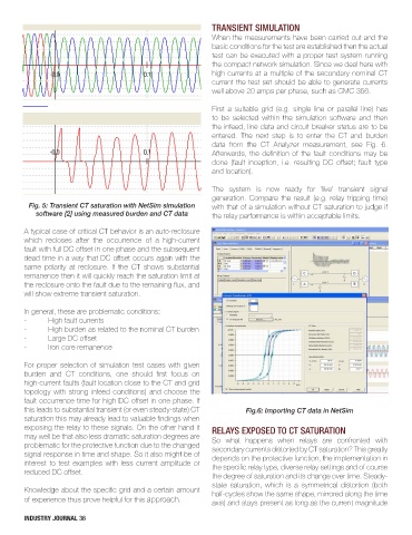
First a suitable grid (e.g. single line or parallel line) has
to be selected within the simulation software and then
the infeed, line data and circuit breaker status are to be
entered. The next step is to enter the CT and burden
data from the CT Analyzer measurement, see Fig. 6.
Afterwards, the definition of the fault conditions may be
done (fault inception, i.e. resulting DC offset; fault type
and location).
The system is now ready for ‘live’ transient signal
generation. Compare the result (e.g. relay tripping time)
Fig. 5: Transient CT saturation with NetSim simulation with that of a simulation without CT saturation to judge if
software [2] using measured burden and CT data the relay performance is within acceptable limits.
A typical case of critical CT behavior is an auto-reclosure
which recloses after the occurrence of a high-current
fault with full DC offset in one phase and the subsequent
dead time in a way that DC offset occurs again with the
same polarity at reclosure. If the CT shows substantial
remanence then it will quickly reach the saturation limit at
the reclosure onto the fault due to the remaining flux, and
will show extreme transient saturation.
In general, these are problematic conditions:
- High fault currents
- High burden as related to the nominal CT burden
- Large DC offset
- Iron core remanence
For proper selection of simulation test cases with given
burden and CT conditions, one should first focus on
high-current faults (fault location close to the CT and grid
topology with strong infeed conditions) and choose the
fault occurrence time for high DC offset in one phase. If
this leads to substantial transient (or even steady-state) CT Fig.6: Importing CT data in NetSim
saturation this may already lead to valuable findings when
exposing the relay to these signals. On the other hand it RELAYS EXPOSED TO CT SATURATION
may well be that also less dramatic saturation degrees are So what happens when relays are confronted with
problematic for the protective function due to the changed secondary currents distorted by CT saturation? This greatly
signal response in time and shape. So it also might be of depends on the protective function, the implementation in
interest to test examples with less current amplitude or the specific relay type, diverse relay settings and of course
reduced DC offset.
the degree of saturation and its change over time. Steady-
state saturation, which is a symmetrical distortion (both
Knowledge about the specific grid and a certain amount half-cycles show the same shape, mirrored along the time
of experience thus prove helpful for this approach. axis) and stays present as long as the current magnitude
INDUSTRY JOURNAL 36