
Page 40 - CARILEC CE Industry Journal_Oct_2019
P. 40
TM
Rigging equipment mechanical ratings typically require a The K-ARM aluminum base can be bolted directly to
5 to 1 safety factor [1]. For most transmission line the pole. The base also features eye nuts which permit
vertical conductor loads, the conventional live line tool the use of strap binders when mounting the K-ARM to
TM
auxiliary arm configurations previously illustrated can composite, steel or concrete poles.
become mechanically “strained”.
In addition to these features, the K-ARM tool
TM
Additionally, under high mechanical loads, pole incorporates the very popular and industry’s original
attachments and saddles will actually dig into the pole. K-CLAMP® which has efficiently, effectively and safely
This can become a noticeable problem when this facilitated live line tool work methods for over
hardware is attached to wood or composite pole twenty-five years. It can accommodate conductor sizes
structures. Other complaints when using traditional live ranging from #4 AWG (5.1 mm/0.2” dia.) to 1192
line tools for this application include: kcmil (34 mm/1.34” dia.) An example of the application
of the K-ARM during a conductor relocation is
TM
• Very time consuming setup. illustrated in Fig. 3.
• Inclement weather requires removal of the tools
and shutdown of the operation.
• Higher tool load capabilities are required.
The new K-ARM live line tool design for application
TM
with 115 kV lines is illustrated in Fig. 2. It is lightweight
and provides improved auxiliary arm stability, strength
and dependable performance even under lightening and
wet conditions.
Fig. 3 - Relocating Conductor to K-ARM TM
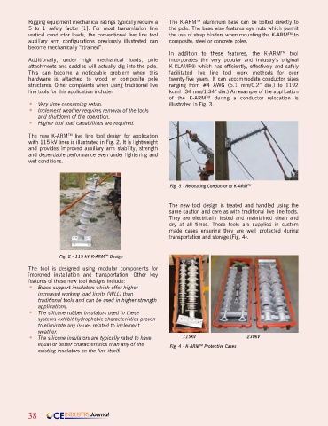
The new tool design is treated and handled using the
same caution and care as with traditional live line tools.
They are electrically tested and maintained clean and
dry at all times. These tools are supplied in custom
made cases ensuring they are well protected during
transportation and storage (Fig. 4).
Fig. 2 - 115 kV K-ARM Design
TM
The tool is designed using modular components for
improved installation and transportation. Other key
features of these new tool designs include:
• Brace support insulators which offer higher
increased working load limits (WLL) than
traditional tools and can be used in higher strength
applications.
• The silicone rubber insulators used in these
systems exhibit hydrophobic characteristics proven
to eliminate any issues related to inclement
weather.
• The silicone insulators are typically rated to have 115kV 230kV
equal or better characteristics than any of the Fig. 4 - K-ARM Protective Cases
TM
existing insulators on the line itself.
38 CE INDUSTRY Journal