
Page 43 - CARILEC CE Industry Journal_Oct_2019
P. 43
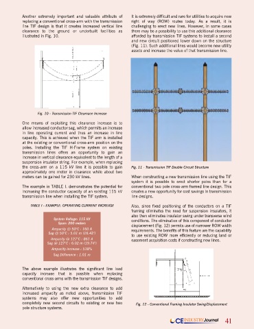
Another extremely important and valuable attribute of   It is extremely difficult and rare for utilities to acquire new
            replacing a conventional cross-arm with the transmission   right of way (ROW) routes today. As a result, it is
            line TIF design is that it creates increased vertical line   challenging to erect new lines. However, in some cases
            clearance to the ground or underbuilt facilities as   there may be a possibility to use this additional clearance
            illustrated in Fig. 10.                             afforded by transmission TIF systems to install a second
                                                                and new circuit positioned lower down on the structure
                                                                (Fig. 11). Such additional lines would become new utility
                                                                assets and increase the value of that transmission line.


                   Fig. 10 - Transmission TIF Clearnace Increase
            One means of exploiting this clearance increase is to
            allow increased conductor sag, which permits an increase
            in line  operating current  and  thus an  increase  in line
            capacity. This is achieved when the TIF arm is installed
            at the existing or conventional cross-arm position on the
            poles. Installing  the TIF H-Frame  system  on  existing
            transmission lines offers an opportunity to  gain  an
            increase in vertical clearance equivalent to the length of a
            suspension insulator string. For example, when replacing
            the cross-arm on a 115 kV line it is possible to gain   Fig. 11 - Transmission TIF Double Circuit Structure
            approximately one meter in clearance while about two
            meters can be gained for 230 kV lines.              When constructing a new transmission line using the TIF
                                                                system it is possible to erect shorter poles than for a
            The example in TABLE I. demonstrates the potential for   conventional two pole cross-arm framed line design. This
            increasing the conductor capacity of an existing 115 kV   creates a new opportunity for cost savings in transmission
            transmission line when installing the TIF system.   line designs.

                TABLE I - EXAMPLE: OPERATING CURRENT INCREASE   Also, since fixed positioning of the conductors on a TIF
                                                                framing eliminates the need for suspension insulators, it
                                                                also then eliminates insulator swing under transverse wind
                           System Voltage: 115 kV               conditions. The elimination of this component of conductor
                             Span: 200 meters
                                                                displacement (Fig. 12) permits use of narrower ROW width
                          Ampacity @ 50°C : 160 A               requirements. The benefits of this feature are the capability
                        Sag @ 50°C : 5.01 m (16.42’)            to use existing ROW more efficiently or reducing land or
                          Ampacity @ 127°C : 861 A              easement acquisition costs if constructing new lines.
                        Sag @ 127°C : 6.02 m (19.74’)
                          Ampacity increase : 538%
                           Sag Difference : 1.01 m


            The above example illustrates the significant line load
            capacity increase that is possible when replacing
            conventional cross-arms with the transmission TIF designs.

            Alternatively to using the new  extra  clearance to add
            increased  ampacity  as  noted above,  transmission TIF
            systems may also offer new opportunities to add
            completely new second circuits to existing or new two   Fig. 12 - Conventional Framing Insulator Swing/Displacement
            pole structure systems.

                                                                                      CE  INDUSTRY Journal    41