
Page 41 - CARILEC CE Industry Journal_Oct_2019
P. 41
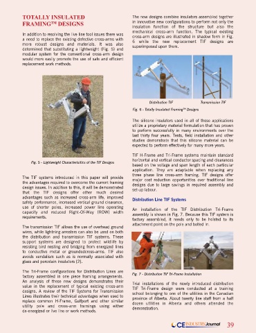
TOTALLY INSULATED                                   The new designs combine insulators assembled together
            FRAMING  DESIGNS                                    in innovative new configurations to perform not only the
                         TM
                                                                insulation function of the structure but also the
                                                                mechanical cross-arm function. The typical existing
            In addition to resolving the live line tool issues there was   cross-arm designs are illustrated in shadow form in Fig.
            a need to replace the existing defective cross-arms with   6 while the new replacement TIF designs are
            more robust designs and materials. It was also      superimposed upon them.
            determined that substituting a lightweight (Fig. 5) and
            modular system for the conventional cross-arm design
            would more easily promote the use of safe and efficient
            replacement work methods.


                                                                        Distribution TIF         Transmission TIF
                                                                Fig. 6 - Totally Insulated Framing  Designs
                                                                                         TM
                                                                The silicone insulators used in all of these applications
                                                                utilize a proprietary material formulation that has proven
                                                                to perform successfully in many environments over the
                                                                last thirty four years. Tests, field installation and other
                                                                studies demonstrate that this silicone material can be
                                                                expected to perform effectively for many more years.

                                                                TIF H-Frame and Tri-Frame systems maintain standard
                                                                horizontal and vertical conductor spacing and clearances
                Fig. 5 - Lightweight Characterisitics of the TIF Designs
                                                                based on the voltage and span length of each particular
                                                                application. They are adaptable when replacing any
                                                                three phase line cross-arm framing. TIF designs offer
            The TIF systems introduced in this paper will provide   major cost reduction opportunities over traditional line
            the advantages required to overcome the current framing   designs due to large savings in required assembly and
            design issues. In addition to this, it will be demonstrated   set-up labour.
            that the TIF designs offer other much desired
            advantages such as increased cross-arm life, improved   Distribution Line TIF Systems
            safety performance, increased vertical ground clearance,
            use of shorter poles, increased power line operating   An installation of the TIF Distribution Tri-Frame
            capacity and reduced Right-Of-Way (ROW) width       assembly is shown in Fig. 7. Because this TIF system is
            requirements.                                       factory assembled, it needs only to be hoisted to its
                                                                attachment point on the pole and bolted in.
            The transmission TIF allows the use of overhead ground
            wires, while lightning arresters can also be used on both
            the distribution and transmission TIF systems. These
            support systems are designed to protect wildlife by
            resisting bird nesting and bridging from energized lines
            to conductive metal or groundedcross-arms. TIF also
            avoids vandalism such as is normally associated with
            glass and porcelain insulators [2].

            The Tri-Frame configurations for Distribution Lines are
            factory assembled in one piece framing arrangements.   Fig. 7 - Distribution TIF Tri-Frame Installation
            An analysis of these new designs demonstrates their   Trial installations of the newly introduced distribution
            value in the replacement of typical existing cross-arm   TIF Tri-Frame design were conducted at a training
            designs. A review of the TIF Systems for Transmission   school belonging to one of the utilities in the Canadian
            Lines illustrates their technical advantages when used to   province of Alberta. About twenty line staff from a half
            replace common H-Frame, Gulfport and other similar   dozen utilities in Alberta and others attended the
            utility pole and cross-arm framings using either    demonstration.
            de-energized or live line or work methods.

                                                                                      CE  INDUSTRY Journal    39