
Page 44 - CARILEC CE Industry Journal_Oct_2019
P. 44
Eliminating the insulator swing displacement also means CONCLUSIONS
that the separation distances between phases and the
structure itself, can be reduced. These reductions in the The replacement of existing deteriorating cross-arms is a
structure width and structure height offer a new growing issue. The need to develop new, safer and more
opportunity to design and construct more compact lines. efficient tools became obvious as utilities deal with the
Compact lines use less materials and require a much constant necessity to maintain dependable and
smaller ROW width, both of which also contribute to line uninterrupted power supply to their Clients. Live line work
construction cost reductions. Compact lines are often also methods are the preferred approach when conducting
considered to be much more aesthetically pleasing to the most maintenance work activities.
general public and can enhance customer relations.
The new tools, equipment and materials discussed offer
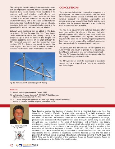
Optional brace insulators can be added to the basic new opportunities for electric utility and contractor
transmission TIF line framings (Fig. 13). These braces operations personnel to effectively and safely meet these
can increase the mechanical load carrying capacity of the
system by up to 80% for some of the designs. The challenging maintenance and system performance
increases capability depends on the angle between the requirements. Since the TIF framings require significantly
less labour to erect compared to traditional cross-arms,
TIF horizontal cross-arm and the supporting brace line crew work activity exposure is greatly reduced.
insulator. [3] This feature may permit increasing line
span lengths. This will require a reduced number of
transmission structures and further reduce line costs. The distribution and transmission line TIF systems and
K-ARM tool are proven to provide many advantages,
TM
benefits and cost savings over conventional equipment.
The new TIF designs also help improve system reliability
and facilitate longer plant service life.
The TIF systems can easily be customized to substitute
various existing or required new framing arrangements
and line voltages.
Fig. 13. Transmission TIF System Design with Bracing
References
[1] Ontario Hydro Rigging Handbook, Canada, 1982
[2] A.J. Carreira. “Insulator Inspection”, 2015 INMR World Congress,
Munich, Germany, October 18-21, 2015
[3] A.C. Baker, “Design and Application of Braced High Voltage Insulator Assemblies”,
DEIS IEEE Electrical Insulating Magazine, March/April 2010
Tony Carreira received his Bachelor of Applied Science in Electrical Engineering from the
University of Waterloo (Ontario, Canada). After graduation Tony held engineering and
management positions for 13 years with Ontario Hydro (now Hydro One). He has been President
of K-LINE INSULATORS LIMITED since 1990 and has an extensive background in the design,
production and application of outdoor polymer insulators. During his career, Tony has also been
involved and has consulted in the areas of transmission and distribution line design,
maintenance, construction and research. He is periodically also called upon to provide course
A. J. (Tony) CARREIRA, material and instruction on insulators to various utility personnel. Tony is a member of the
P. Eng. SMIEEE Association of Professional Engineers of Ontario, CIGRE, IEC, CSA, CIGELE and is a Senior
Member of IEEE. He is chairman and/or a member of various committees in these and other
organizations. He has authored or coauthored numerous technical papers and has been a
presenter of technical papers at various international conferences including ICOLIM, IEEE and
INMR. Tony was the 2014 recipient of the prestigious Claude de Tourreil Memorial Award for
Lifetime Achievement in the Field of Electrical Insulators.
42 CE INDUSTRY Journal