
Page 42 - CARILEC CE Industry Journal_Oct_2019
P. 42
During the trials, the line crews were impressed to connection points on the TIF system facilitate attachment
discover that the time to lift the preassembled unit and of standard clamps and conductors directly to the TIF
bolt it into place at the top of the pole only took about 6 system. This feature eliminates the need for suspension
minutes. This is a significantly reduced installation time insulator strings.
when compared to the construction of a traditional
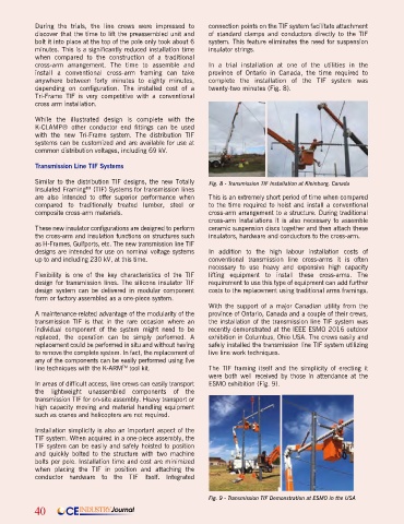
cross-arm arrangement. The time to assemble and In a trial installation at one of the utilities in the
install a conventional cross-arm framing can take province of Ontario in Canada, the time required to
anywhere between forty minutes to eighty minutes, complete the installation of the TIF system was
depending on configuration. The installed cost of a twenty-two minutes (Fig. 8).
Tri-Frame TIF is very competitive with a conventional
cross arm installation.
While the illustrated design is complete with the
K-CLAMP® other conductor end fittings can be used
with the new Tri-Frame system. The distribution TIF
systems can be customized and are available for use at
common distribution voltages, including 69 kV.
Transmission Line TIF Systems
Similar to the distribution TIF designs, the new Totally Fig. 8 - Transmission TIF Installation at Kleinburg, Canada
Insulated Framing (TIF) Systems for transmission lines
TM
are also intended to offer superior performance when This is an extremely short period of time when compared
compared to traditionally treated lumber, steel or to the time required to hoist and install a conventional
composite cross-arm materials. cross-arm arrangement to a structure. During traditional
cross-arm installations it is also necessary to assemble
These new insulator configurations are designed to perform ceramic suspension discs together and then attach these
the cross-arm and insulation functions on structures such insulators, hardware and conductors to the cross-arm.
as H-Frames, Gulfports, etc. The new transmission line TIF
designs are intended for use on nominal voltage systems In addition to the high labour installation costs of
up to and including 230 kV, at this time. conventional transmission line cross-arms it is often
necessary to use heavy and expensive high capacity
Flexibility is one of the key characteristics of the TIF lifting equipment to install these cross-arms. The
design for transmission lines. The silicone insulator TIF requirement to use this type of equipment can add further
design system can be delivered in modular component costs to the replacement using traditional arms framings.
form or factory assembled as a one-piece system.
With the support of a major Canadian utility from the
A maintenance-related advantage of the modularity of the province of Ontario, Canada and a couple of their crews,
transmission TIF is that in the rare occasion where an the installation of the transmission line TIF system was
individual component of the system might need to be recently demonstrated at the IEEE ESMO 2016 outdoor
replaced, the operation can be simply performed. A exhibition in Columbus, Ohio USA. The crews easily and
replacement could be performed in situ and without having safely installed the transmission line TIF system utilizing
to remove the complete system. In fact, the replacement of live line work techniques.
any of the components can be easily performed using live
line techniques with the K-ARM tool kit. The TIF framing itself and the simplicity of erecting it
TM
were both well received by those in attendance at the
In areas of difficult access, line crews can easily transport ESMO exhibition (Fig. 9).
the lightweight unassembled components of the
transmission TIF for on-site assembly. Heavy transport or
high capacity moving and material handling equipment
such as cranes and helicopters are not required.
Installation simplicity is also an important aspect of the
TIF system. When acquired in a one-piece assembly, the
TIF system can be easily and safely hoisted to position
and quickly bolted to the structure with two machine
bolts per pole. Installation time and cost are minimized
when placing the TIF in position and attaching the
conductor hardware to the TIF itself. Integrated
Fig. 9 - Transmission TIF Demonstration at ESMO in the USA
40 CE INDUSTRY Journal