
Page 57 - CARILEC CE Industry Journal_Oct_2019
P. 57
Engine OEMS have or should have very defined
acceptance criteria for engine balance, maximum allowed
peak pressures as well as standard deviations.
A typical engine report from the collected pressure data
will show items such as IMEP (Indicated Mean Effective
Pressure) or Mean Indicated Pressure (MIP), IHP
(Indicated Horsepower), Combustion Start Angle,
Maximum Pressure Rise Rate (MPRR), Peak Firing
Pressure Statistical data from at least 30 cycles, the Delta
or difference between the cylinder average and the engine Fig. 17 - Mechanical Impact Example
average. Peak Firing Pressure Angle (PFPA), as well as
other pressure points along the P-T curve have important
value. Typically, your engine OEM manual will represent
this acceptance criteria as ±5 bar from the certified value
at any one cylinder.
The author frequently reviews combustion related data
where measured plant data is nowhere close to these
acceptance criteria, as much as 28% in some instances.
Fig. 16 is an example engine report with good peak
pressure balance.
Fig. 18 - Gas Noise Example
Different engine components and their related faults are
determined by utilizing different frequency ranges and/or
filtering in the system hardware. When this type of data is
“phased” to crankshaft position, the component making
the noise can be determined and assessed as to whether
the noise is normal or abnormal (Fig. 19). This analysis
technique applies to 4-stroke, 2-stroke or high, medium or
slow speed engines. In each case, the data acquisition and
interpretation process remains the same.
Fig. 16 - Engine Combustion Report
Proven Technology
When collecting and analyzing vibration data from a
reciprocating machine, such as a Diesel Engine, there are
two basic types of vibration - Free Vibration and Forcing
Function Vibration.
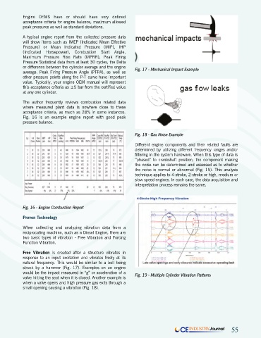
Free Vibration is created after a structure vibrates in
response to an input excitation and vibrates freely at its
natural frequency. This would be similar to a bell being
struck by a hammer (Fig. 17). Examples on an engine
would be the impact measured in “g” or acceleration of a Fig. 19 - Multiple Cylinder Vibration Patterns
valve hitting the seat when it is closed. Another example is
when a valve opens and high pressure gas exits through a
small opening causing a vibration (Fig. 18).
CE INDUSTRY Journal 55